
Star Delta Forward Reverse Wiring Diagram Pdf Wiring Technology
Star/wye connection and delta connection are the two different methods which are used for connecting 3 phase system. In this video, we'll learn following in detail. 1. Star Connection. 2. Delta connection. 3. Voltage and current relationship in both the connections. 4.
The Beginner's Guide to Wiring a StarDelta Circuit Factomart Singapore
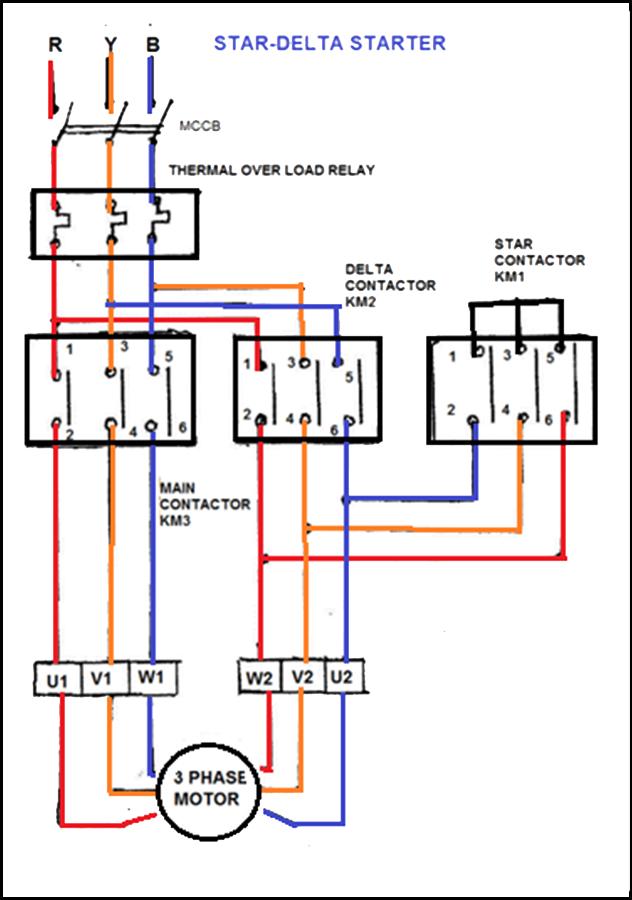
3. Size of Star Contractor. The third contactor is the star contactor and that only carries star current while the motor is connected in star. The current in star is 1/ √3= (58%) of the current in delta, so this contactor can be AC3 rated at one third (33%) of the motor rating. Size of Star Contactor= IFL x 0.33.
Star Delta Starter Wiring Diagram
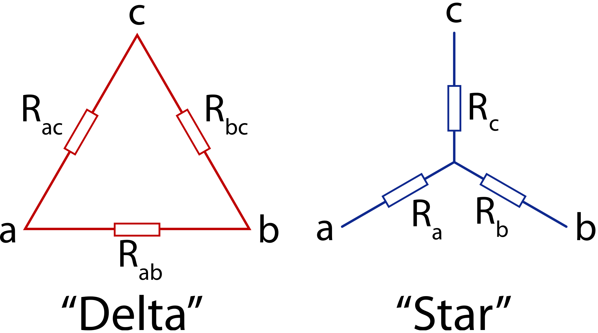
Star Delta Conversion. We know the basic of series, parallel or combo of series and parallel connection but Y-Δ is another little bit complex configuration of components. The 3-phase networks have three wires and usually, the networks are connected in star & delta configuration.The 3 phase supply or the load connected in either formation can be converted into its equivalent counterpart.

WAZIPOINT Engineering Science & Technology 03/31/22
Delta to Wye Conversion Suppose it is more convenient to work with a wye network in a place where the circuit contains a delta configuration. We superimpose a wye network on the existing delta network and find the equivalent resistances in the wye network. For terminals 1 and 2 in Figs. 1 and 2 𝐑 = 𝐑 𝐑 𝐑 + 𝐑 + 𝐑 𝐑 =
Diysity Star Delta Power Wiring Diagram
Delta - Star connection Aim of experiment: To study the properties of delta-star connection. Apparatus 1. DC circuit training system 2. Set of wires. 3. DC Power supply 4. Digital A.V.O. meter Theory In solving networks (having considerable number of branches) by the application of Kirchhoff's Laws, one sometimes experiences great difficulty

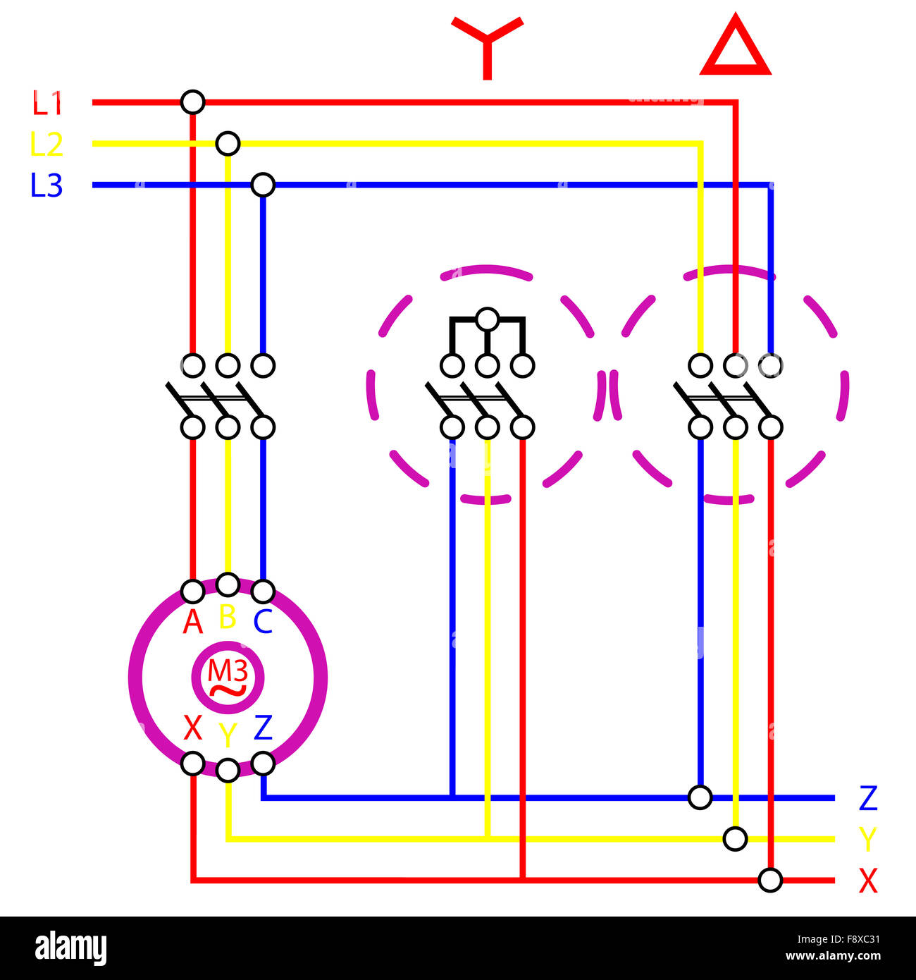
🔴 Stardelta connection of a three phase Induction Motor 😍 Save, share and please follow us
Fig. 2, Line and phase current waveforms in a delta connected induction motor. same delta connected motor, but mathemat-ically represents the delta by its star equiv-alent as shown in Fig. 3. The benefit of using an equivalent star for simulation purposes is the simpler 3-step current waveform of Fig. 3 compared to the 4-step current waveform.
Wiring Diagram Of Star Delta Motor Wiring23
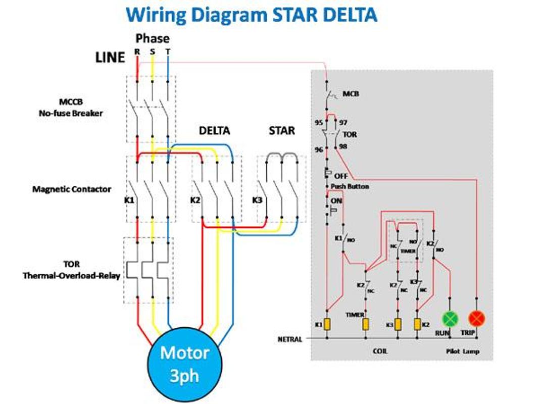
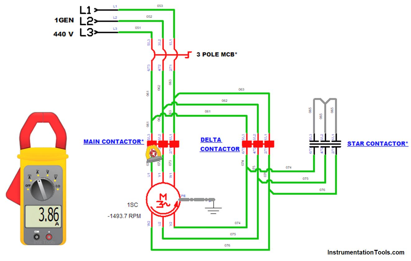
The Star Delta starting method is a motor starting mechanism that minimizes the large amount of starting current that motors draw in. The Star Delta, as the name suggests basically involves feeding the motor with 1/√3 (58%) of the full load current until it attains speed then applying the full load current. It is required three contactors i.e.
Siemens Star Delta Starter Wiring Diagram Pdf Talia Copeland
known as star connection. But these star and delta connections can be transformed from one form to another. For simplifying complex network, delta to star or star to delta transformation is often required. Delta To Star Conversion The replacement of delta or mesh by equivalent star connection is known as delta - star transformation. The two.
Star Delta Starter Wiring Diagram Explanation Wiring View and Schematics Diagram
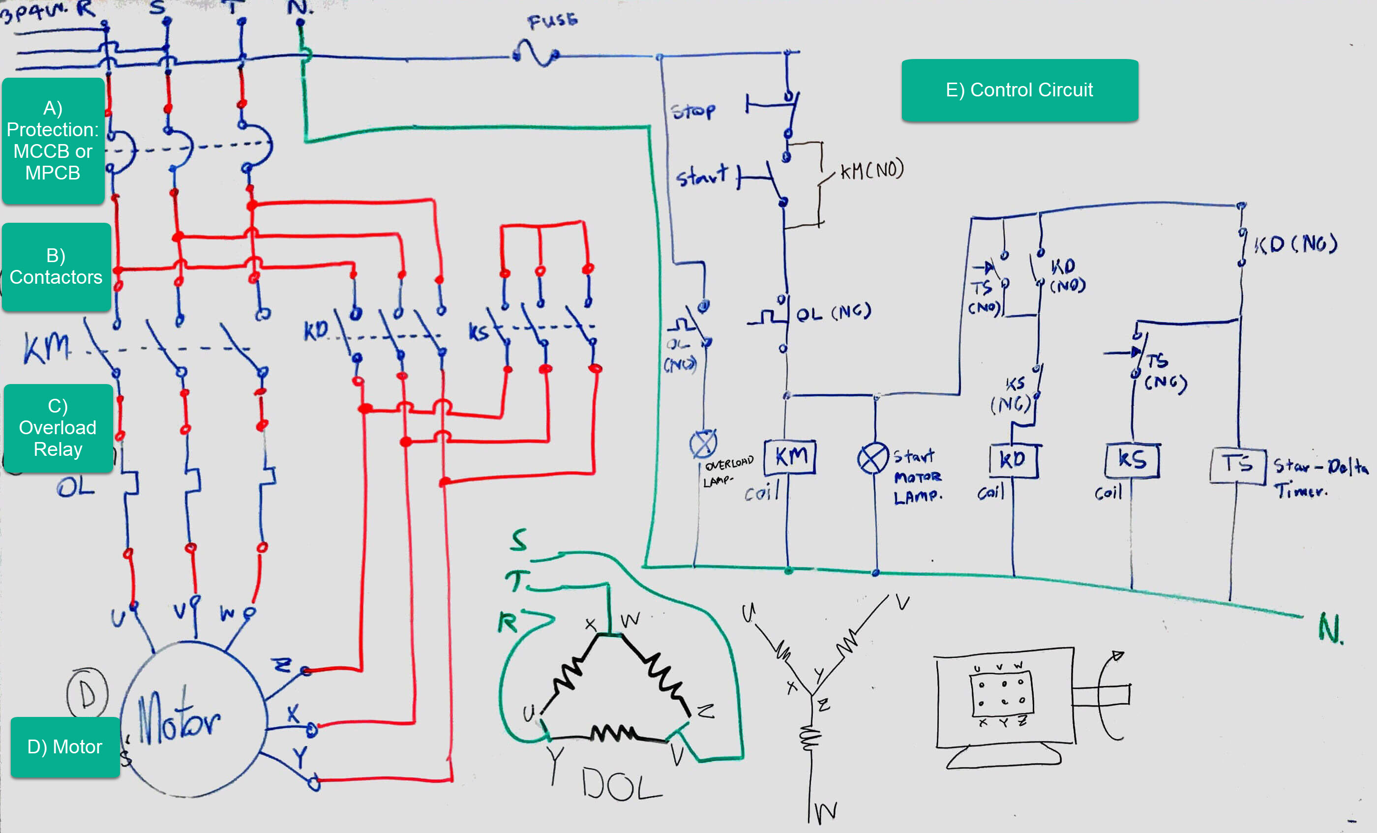
The power and control circuits of a star-delta starter are discussed in this article with the help of an actual star-delta starter wiring diagram.. Terminals. (TB-X1) For motor connection. Control circuit wiring.. Star-Delta starter wiring diagram PDF. star delta panel-wiring diagram Download. Star delta starter circuit Download.
Difference between Star and Delta Connections Engineering Tutorial
INTRODUCTION 15 Star/Delta connection is an arrangement of passive elements R, L and C such that the formed shape resembles a star or a delta symbol. These connection are neither series and nor parallel. Such connections are simplified using star-to-delta or delta-to-star conversion. Such connections are found in complex DC circuits, full.

Star Delta Transformer Wiring Diagram
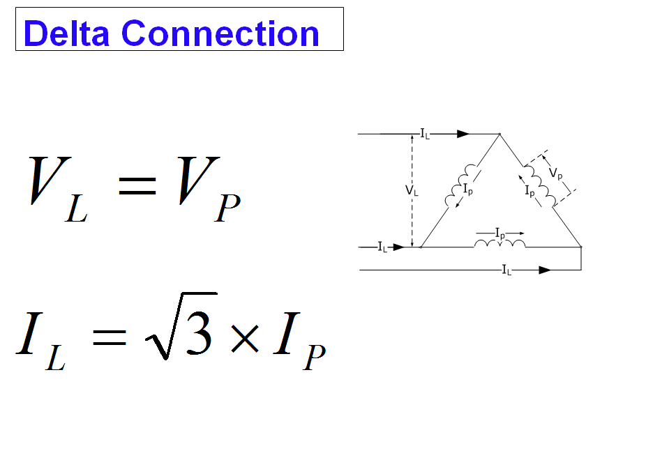
Wye Connection and Delta Connection. The former method of connecting the source voltages together is called a delta connection (or δ connection) because a δ is formed. The latter form of connection is called Y connection (wye connection) or star connection. Note that in delta connection there are only three wires (there is no place for a.

StarDelta Connection EDIBON
Star and Delta connections are two types of connections used in 3-phase circuits. In a Star Connection, the system has a neutral wire, and the line voltage is root three times the phase voltage. It is a balanced circuit connection. In a Delta Connection, there is no neutral wire, and the line voltage is equal to the phase voltage.
star delta connection Stock Photo Alamy
By Ravi Teja. Star and Delta Connections are the two types of connections in a 3 - phase circuits. A Star Connection is a 4 - wire system and a Delta Connection is a 3 - wire system. Before going in to details of the Star Connection, Delta Connection and comparing those two, let us have a very brief note on three - phase electric power.
Comparison between Star and Delta Connections Electrical for Us
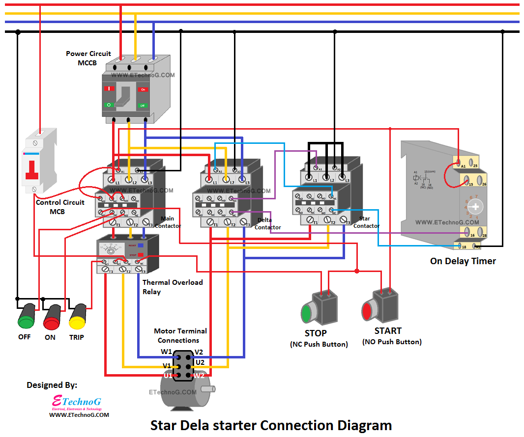
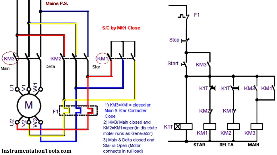
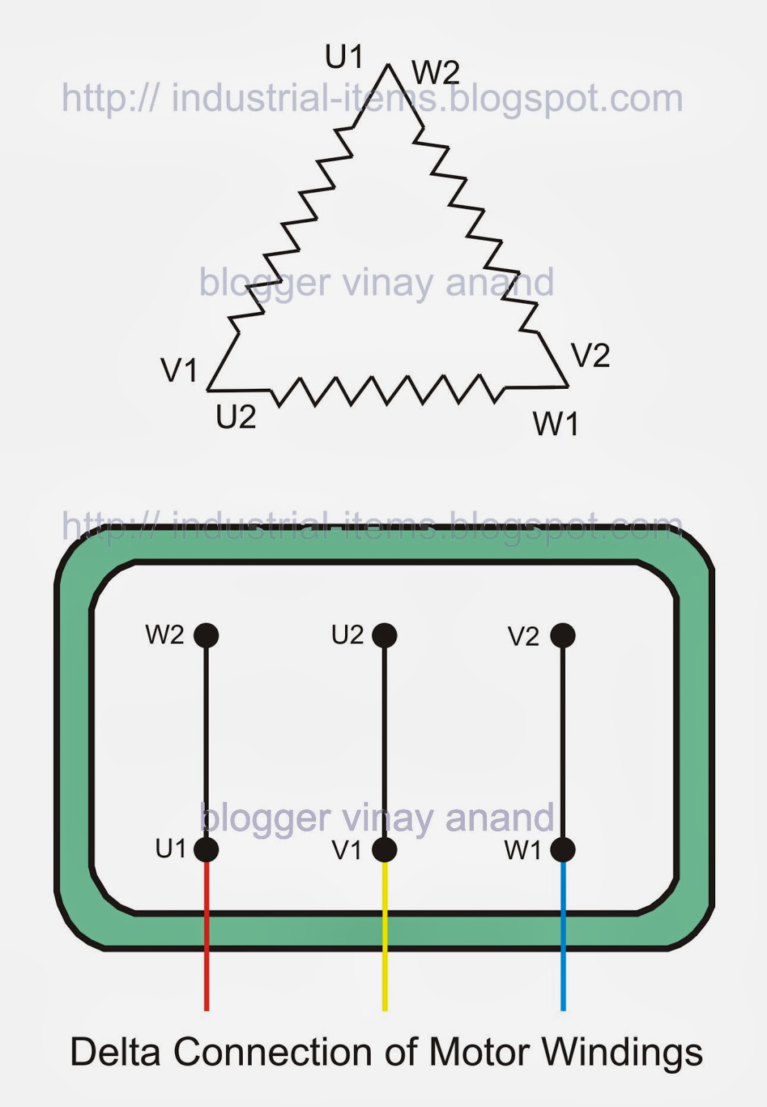
A Star-Delta starter is an electromechanical device used to start and control the speed of a three-phase induction motor. This starter employs the star-delta (Y-Δ) method for starting the motor, which involves changing the motor's winding connection from a Star configuration to a Delta configuration once the motor reaches a certain speed.

Star Delta Starter Connection Diagram and Wiring ETechnoG
INTRODUCTION. Star/Delta connection is an arrangement of passive elements R, L and C. such that the formed shape resembles a star or a delta symbol. These connection are neither series and nor parallel. Such connections are simplified using star-to-delta or delta-to-star conversion. Such connections rectifiers.
GK, Current Affairs, Tutorials & Articles Star Delta Starter Theory
Star-Delta Connection Overview. In this type of transformer connection, then primary is connected in star fashion while the secondary is connected in delta fashion as shown in the Figure 1 below. The voltages on primary and secondary sides can be represented on the phasor diagram as shown in the Figure 2 below.